


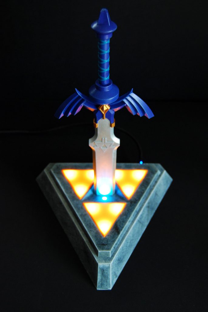
I’m a big Zelda fan since the first one, I always wanted a cool Zelda themed object. As I like retrogmaing, swords and shiny glowing stuff, it was natural that I build this retrogame station with a Raspberry Pi and Recalbox, that boots when putting the sword into. You can see it in action on my youtube channel.

COMPONENTS_
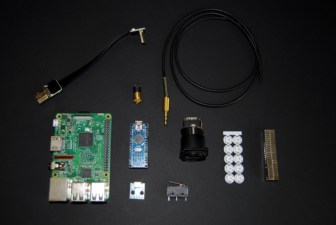
For the electronics, I’ve used :
- – A Raspberry Pi3B (I advise you to use a Pi3B+ for cooling purpose)
- – An Arduino Nano
- – A Micro USB connector
- – A micro-switch
- – A Neutrik HDMI connector
- – A HMDI ribbon
- – 11 adressable LEDs
- – 2 squared neodyme magnets 5*2
- – A male Jack cable
- – A femal Jack connector
3D PRINTED PIECES_
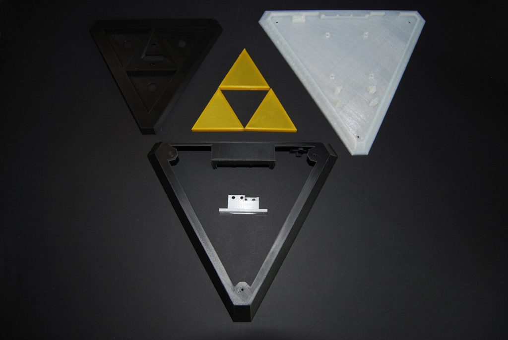
This project is composed by 2 parts : The pedestal where the Raspberry Pi stands and the sword.
- I decomposed the case in 3 parts :
- – Base
- – Body
- – Lid
There are other pieces for the switch, the HDMI and the Triforce.
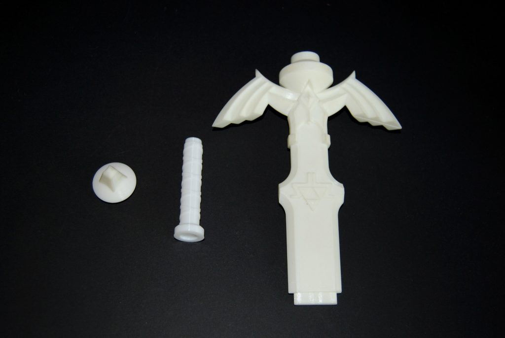
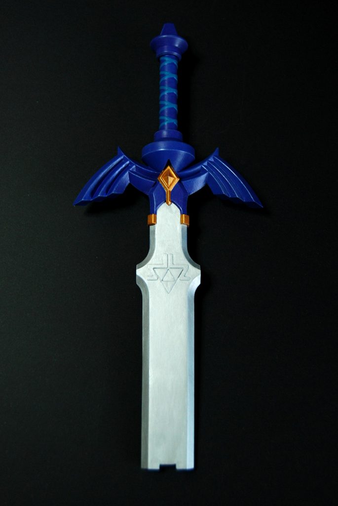
The sword has 6 pieces :
- – The body in 2 parts
- – The pommel and grip, with a piece to attach them
- – The end of the sword where the magnet fits
ARDUINO, LEDS AND CODE_
I start by preparing LEDs and Arduino, I have to install the code.
For this project, I need 2 libraries : Adafruit neopixel and Arduino thread.
There are 11 LEDs, 9 yellows for the Triforce et 2 blues that will light the sword. I wanted them to fade-in fade-out but at 2 different frequences. I’ll plug DATA cable to PIN 5.
Here is the code :
#include <Adafruit_NeoPixel.h>
#include <Thread.h>

//define NeoPixel Pin and Number of LEDs
#define PIN 5
#define NUM_LEDS 11

uint8_t brightY = 255;    // valeur initiale du brightness jaune
uint8_t brightB = 255;    // valeur initiale du  brightness bleu
int fadeSensY = -1;       // sens du fade yellow Out = -1, In = +1
int fadeSensB = -1;       // sens du fade blue Out = -1, In = +1
uint8_t minBrightY = 50;   // valeur min du brightness yellow
uint8_t maxBrightY = 255; // valeur max du brightness yellow
uint8_t minBrightB = 25;   // valeur min du brightness blue
uint8_t maxBrightB = 255; // valeur max du brightness blue


//  création NeoPixel strip
Adafruit_NeoPixel strip = Adafruit_NeoPixel(NUM_LEDS, PIN, NEO_GRB + NEO_KHZ800);

// création tâches leds
Thread ledsJaunes = Thread();
Thread ledsBleues = Thread();


// fonction fade in/out pour les leds jaunes
void fadeInOutYellow() {
  uint32_t rgbcolor = strip.ColorHSV(10922, 255, brightY);
  strip.fill(rgbcolor, 0, 9);
  strip.show(); // This sends the updated pixel color to the hardware.
  brightY = brightY + fadeSensY;

  if (brightY <= minBrightY) {
    fadeSensY = 1;
  }

  if (brightY >= maxBrightY) {
    fadeSensY = -1;
  }
}

// fonction fade in/out pour les leds bleues
void fadeInOutBlue() {
  uint32_t rgbcolor = strip.ColorHSV(32768, 255, brightB);
  strip.fill(rgbcolor, 9, 2);
  strip.show(); // This sends the updated pixel color to the hardware.
  brightB = brightB + fadeSensB;

  if (brightB <= minBrightB) {
    fadeSensB = 1;
  }

  if (brightB >= maxBrightB) {
    fadeSensB = -1;
  }
}


void setup() {
  // start the strip and blank it out
  strip.begin();
  strip.clear();

  // affecte une fonction à une tâche
  ledsJaunes.onRun(fadeInOutYellow);
  ledsBleues.onRun(fadeInOutBlue);

  // initialise l'interval d'exécution de la tâche
  ledsJaunes.setInterval(20);
  ledsBleues.setInterval(10);
}

void loop() {

  if (ledsJaunes.shouldRun()) ledsJaunes.run();

  if (ledsBleues.shouldRun()) ledsBleues.run();

}
THE BUILD_
After a lot of sanding and painting, I can start building it.
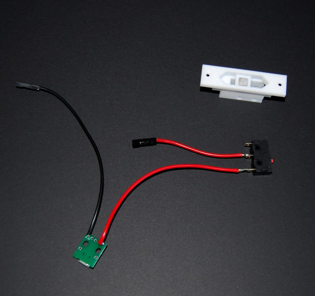
First thing to do is making the switch.
I soldered a red wire from micro-USB Vbus to microswitch C (1) pin then a Dupont wire from microswith NO (2) pin which goes to raspberry 5V GPIO. Then a black Dupont wire to micro-USB GND which goes to Raspberry GND GPIO.
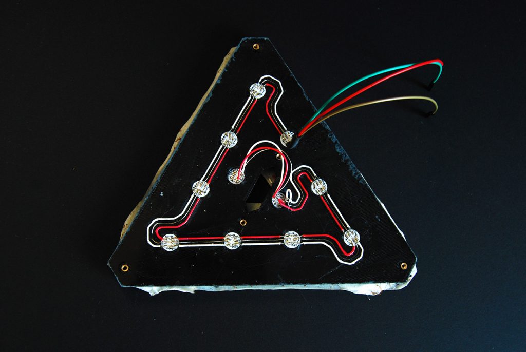
Now the LEDs.
Pretty easy to install, I put the LEDs into holes, and the wires into gutters .
Beware that LEDs has In and Out.
I can now start the body.
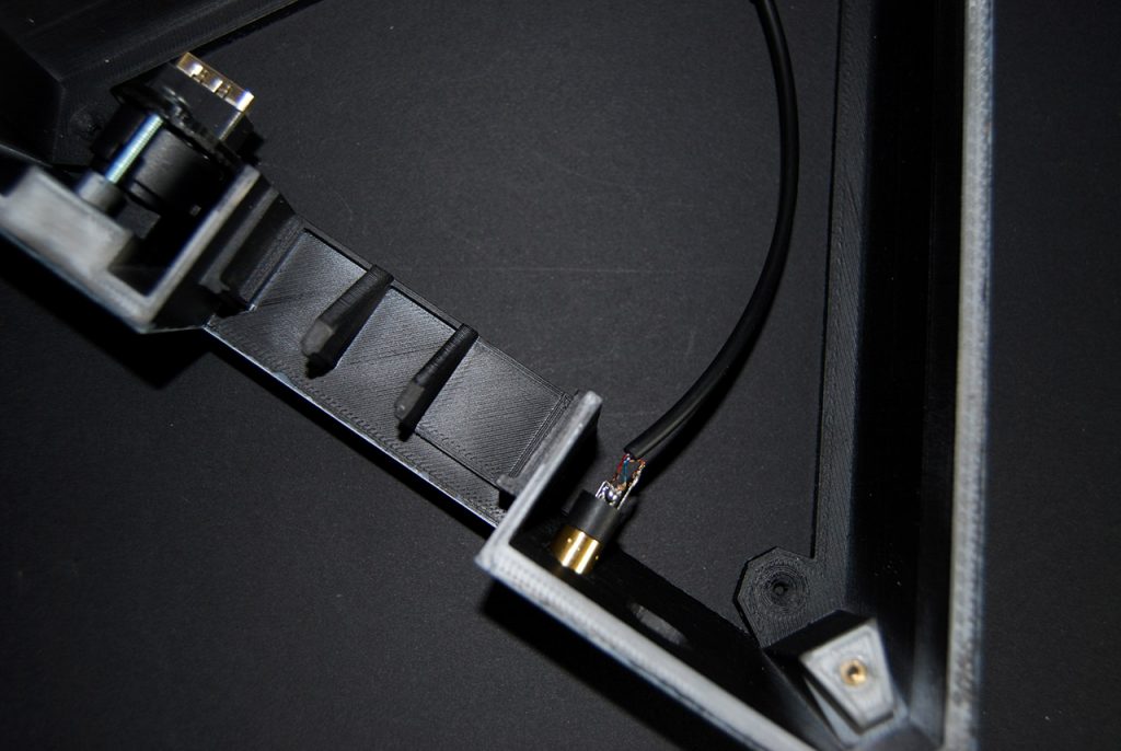
I’ve install the femal Jack connector in place and soldered the male Jack cable. Then installed the HDMI with his support, screwed to the body.
This time I can put the body and lid together and mount the switch.
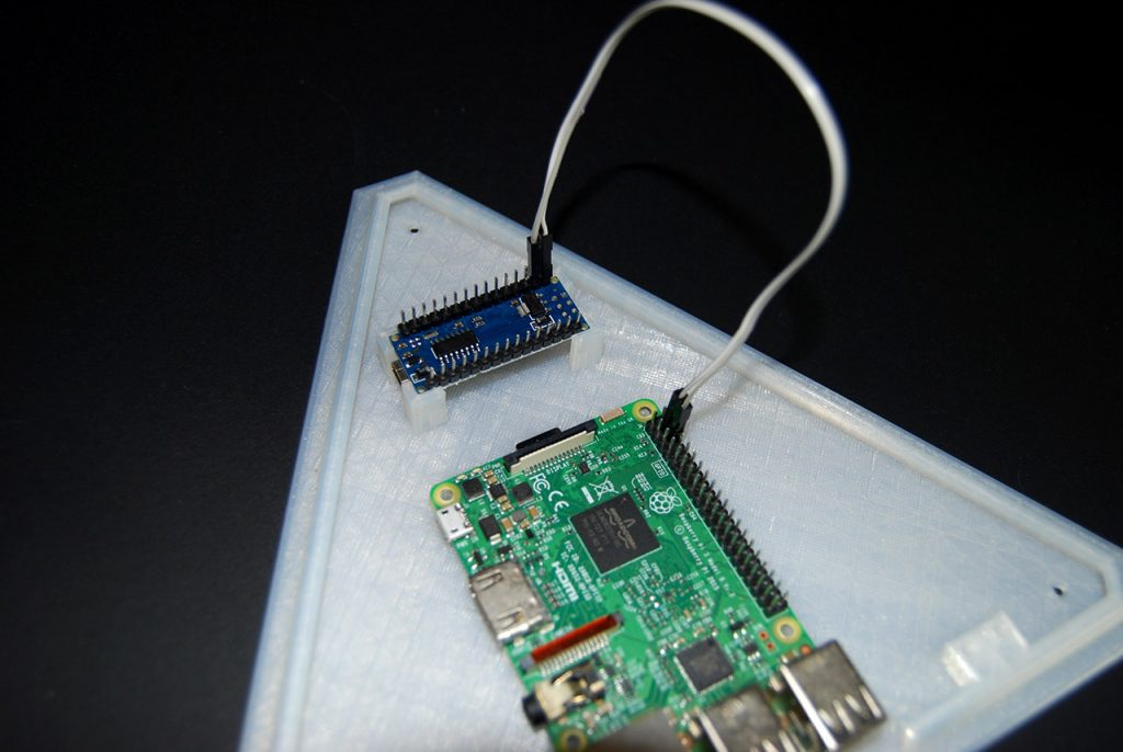
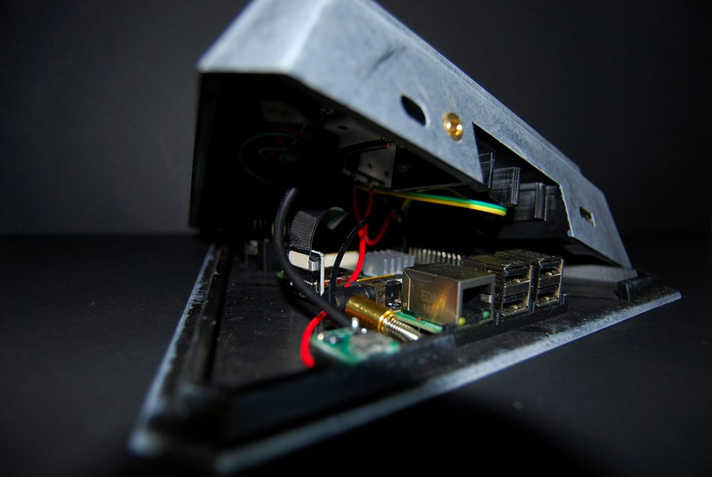
Now the base : I put the Raspberry in place and the Arduino Nano. I plug the Nano GND to the Pi GND GPIO and Nano Vin to 5V GPIO.
I finish to plug everything HDMI, Jack etc, red microswitch wire goes to GPIO 5V and black wire to GPIO GND.
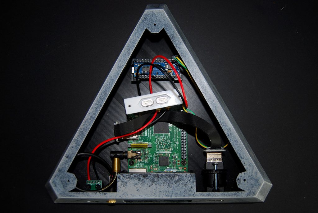
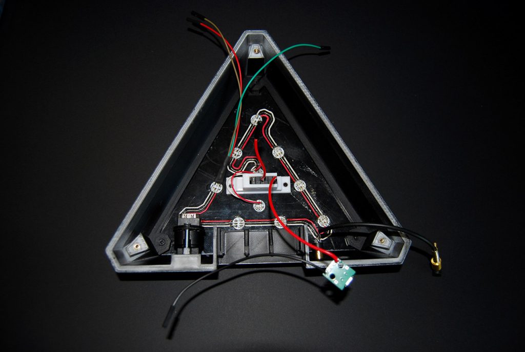
Once mounted, it should look like this. This pictures only shows how it should look on the inside, obviously, the lid must be installed before the rest.
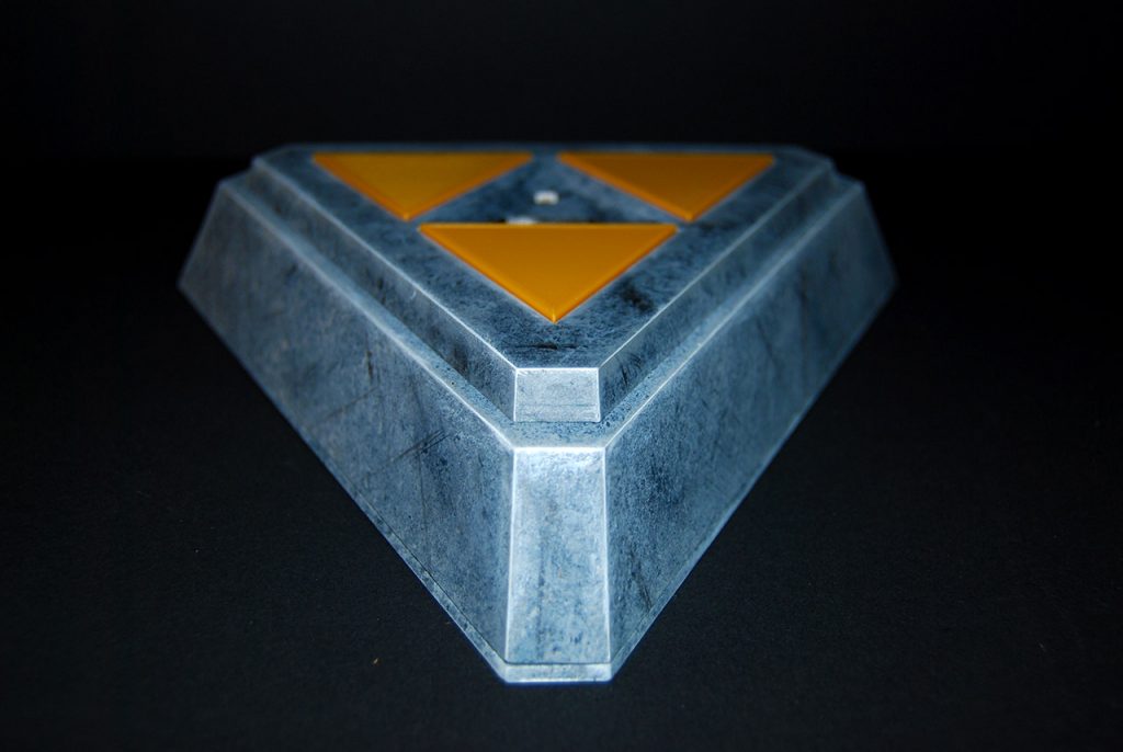
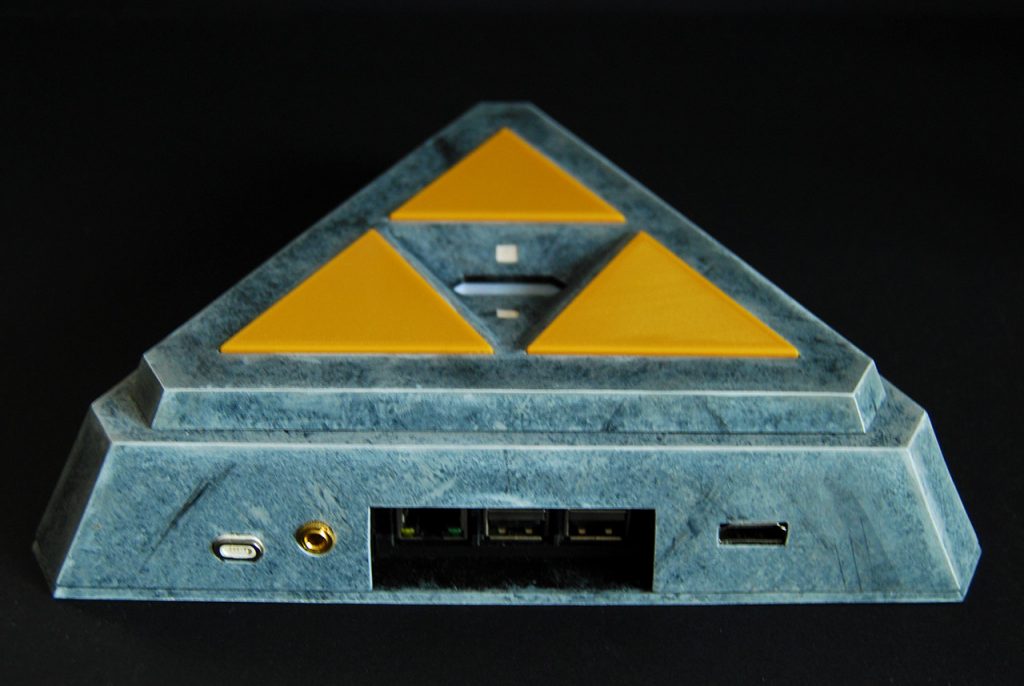

CONCLUSION_
Surely my favorite project, lots of hours on conception, printing, prototyping, and I’m still improving it. It was a long time since I touched a pencil, but clearly did the job !
I hope this B_log was useful, it’s now time to say :
