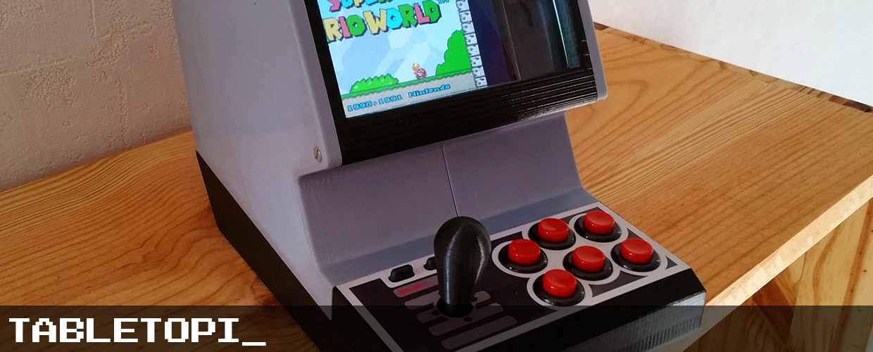
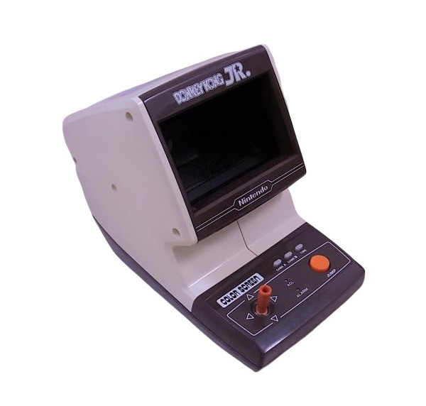
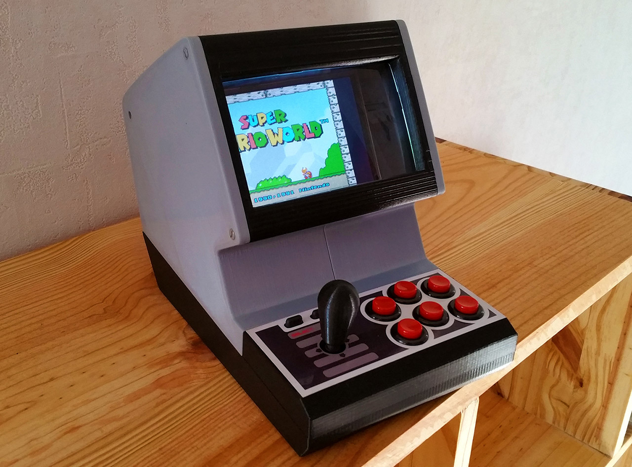
If there is one object I’d like to have, it’s certainly a Tabletop from Nintendo. I remember playing one of those when I was about ten years old and really enjoyed playing this beauty. The problem is that today, I’m not sure of which kidney I’m going to sell to get one in good conditions. So, I had to build one by myself.
COMPONENTS_
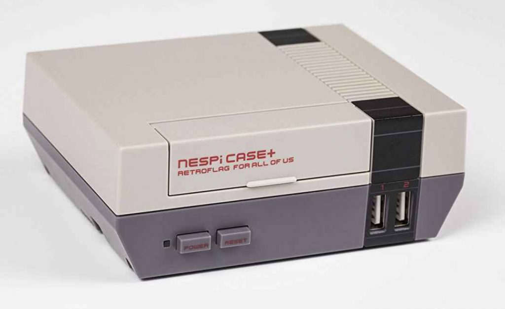
For this project, the components are pretty basic. The trick is the use of a NESPI case+ to save time (and money) on electronics. Note that it’s possible to make one with the NESPI Case basic.
So we have :
- – A NESPI case+
- – A Raspberry PI ( used a 3B+ for thermal purpose )
- – 6 red Sanwa SDM-18 push buttons ( the same one I used in my Pi_Commander )
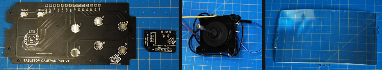
- – A small joystick like CV4-YQ-04R2G ( exists under several names, with better quality )
- – A NES “START SELECT” silicone buttons and some protoboard to make the contactors
- – An 800×480 HDMI 5″ screen
- – A Flat HDMI ribbon ( the same one I used in my Pi_Commander )
- – A PAM 8302 for sound
- – A rectangular speaker, salvaged from an old screen with integrated speakers
- – In my souvenirs, there was a magnifying lens, so I get a Fresnel lens from the Quanum FPV V2 upgrade which got the perfect size for this project. Not mandatory, but gives an HUGE plus to the experiment.
Note that this is a first version. I’m finalizing the V2 which should cost less and have some improvements such as :
- – Custom PCB with soft touch buttons
- – An analog stick (I don’t really like them, I prefer “clicky sticks”, If you think it’s a bad idea, let me know ! )
- – Some ( slight ) modifications to the look
- – getting rid of the NESPI case thanks to a Custom PCB for power.
- – Changing the lens with one easier to find.
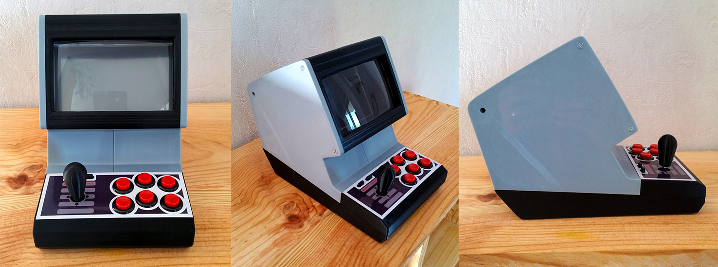
3D PRINTS_
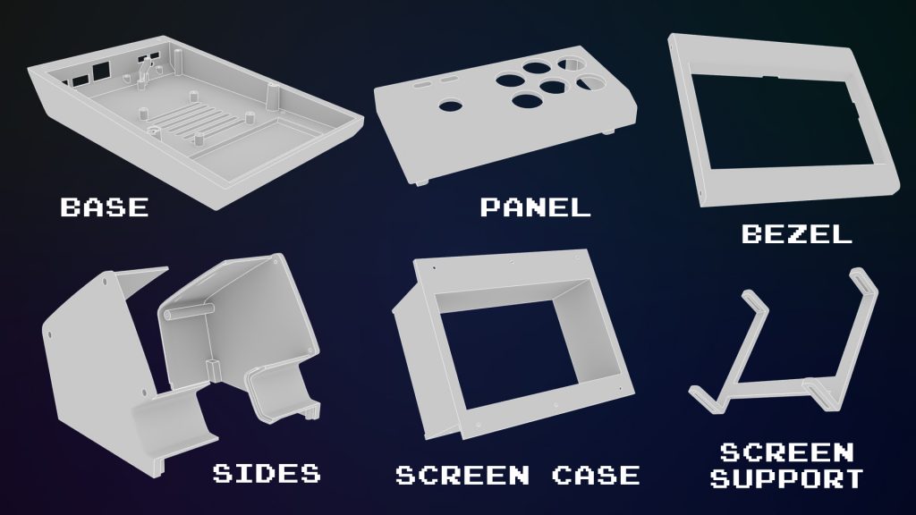
The TabletoPi_ is composed by 6 parts :
- – The base where the electronics goes
- – The panel
- – The bezel
- – The screen case
- – The sides
- – And the support screen
On the left side, I’ve made some place to put the speaker. This place is adapted to my speaker. If you want to make this project, keep in mind that you’ll have to adapte this place for your speaker.
ELECTRONICS_
To begin, I had to make the NESPI case wires longer for about 10cm, for them to be able to reach the GPIO. To avoid mistakes, I kept the same colors.
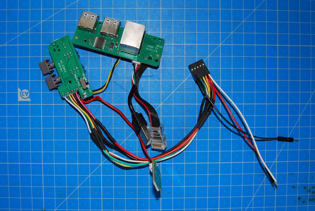
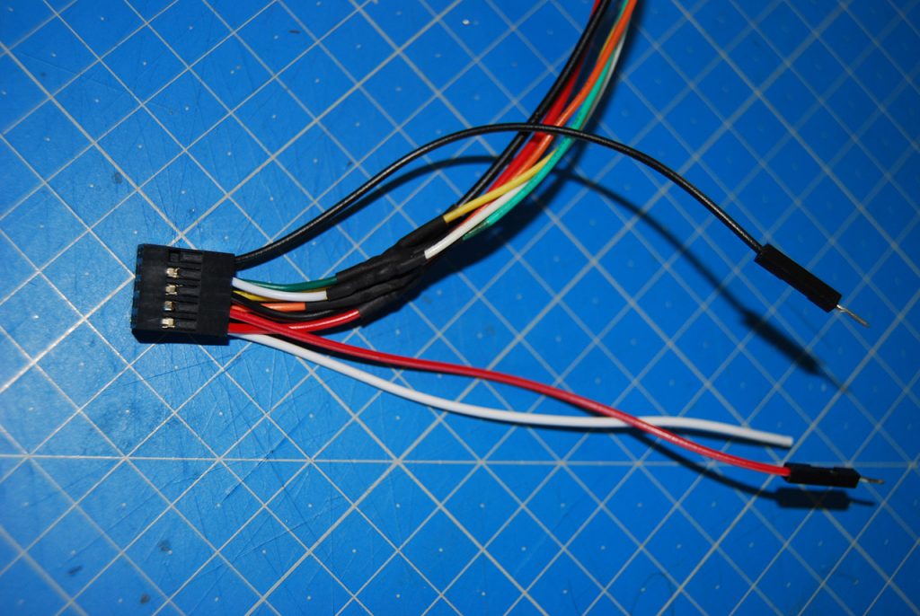
Then I added wires on the NESPI Case GPIO block. One red Dupont in the empty slot whick goes to the second 5V, to supply the screen, and a white wire on the empty 3.3V slot that will supply the PAM8302. A black Dupont which goes on the GND empty slot to ground the screen. You will find the full GPIO diagram a little further.
To create START and SELECT, I used a piece of protoboard where I put some tin to make the contacts. I’ve connected ZABC with a red Dupont at the end for positive START and VWXY with a brown Dupont at the end for positive SELECT, at line 26 then connected GND to TUVWXYZABC with a black Dupont on line 25.
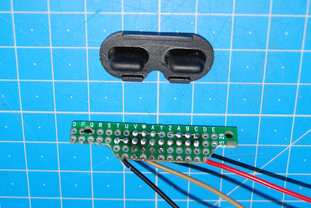
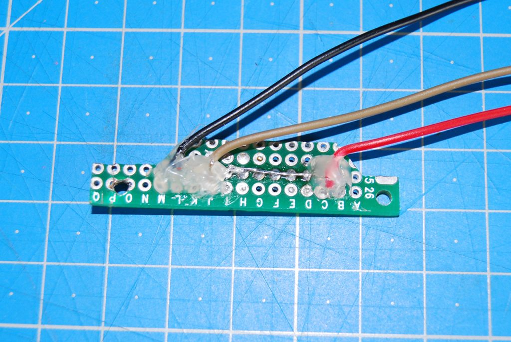
Then I’ve secured the whole thing with hot glue, drilled at good distance to screw the board to the 3D printed base.
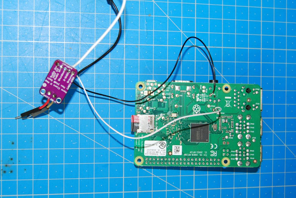
Finally, I soldered a white wire to PP25 pad on the Pi, which goes to the PAM audio + and a black wire from PP6 to the Audio – , a black Dupont to the PAM GND and soldered the NESPI wire block white wire ( 3.3V ) to PAM Vin.
THE BUILD_
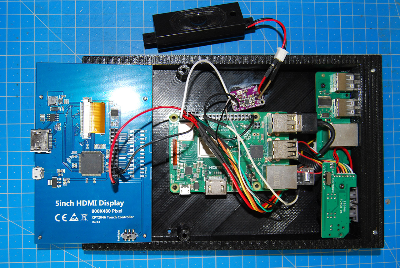
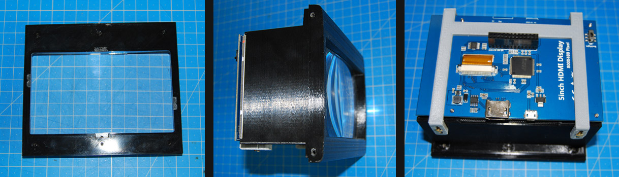
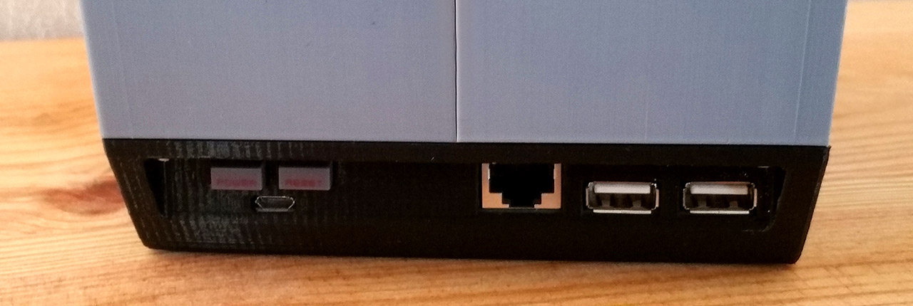
At this point, the build is pretty simple. I just needed to mount the electronics of the NESPI, starting by the micro-usb port, plugging everything to the Pi and mount the Pi. For the screen, I’ve installed the lens into the bezel, mount the bezel to the screen case and install the TFT on the other side of the screen case. Then the screen support.
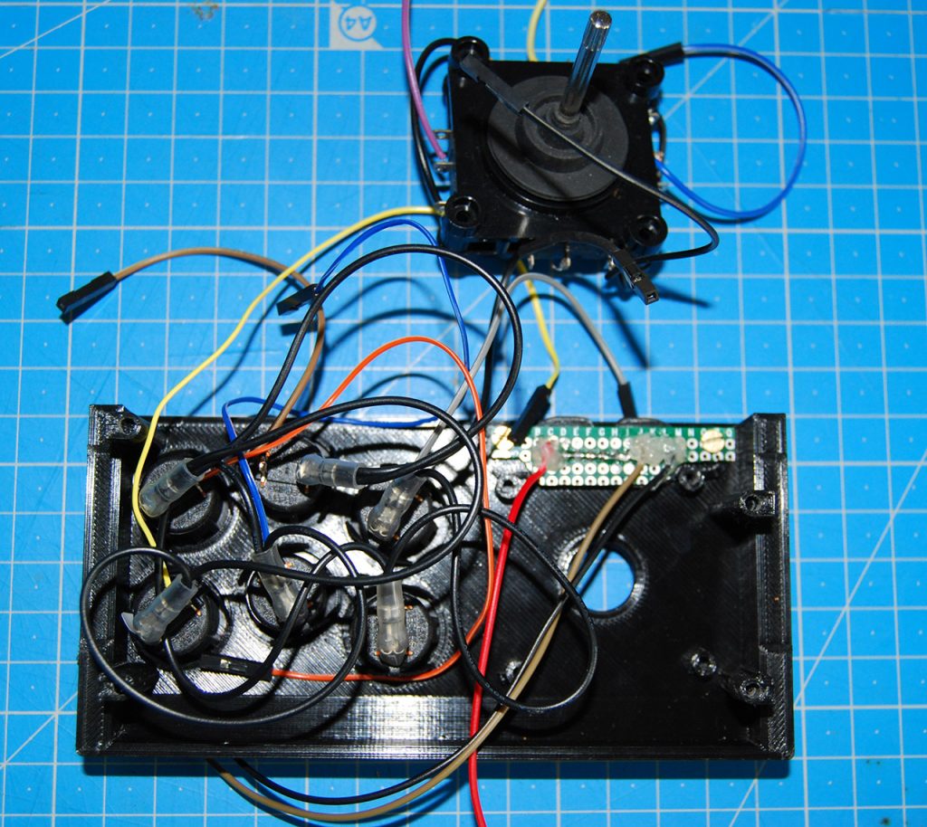
It’s now time to wire the panel. It’s a basic arcade wiring. Mount the Sanwas, one Dupont soldered on one pin of each buttons, a ground chain and the same thing to the stick. To mount START SELECT, I just have not to forget to put the silicone buttons BEFORE the protoboard (hem). Then screw the joystick.
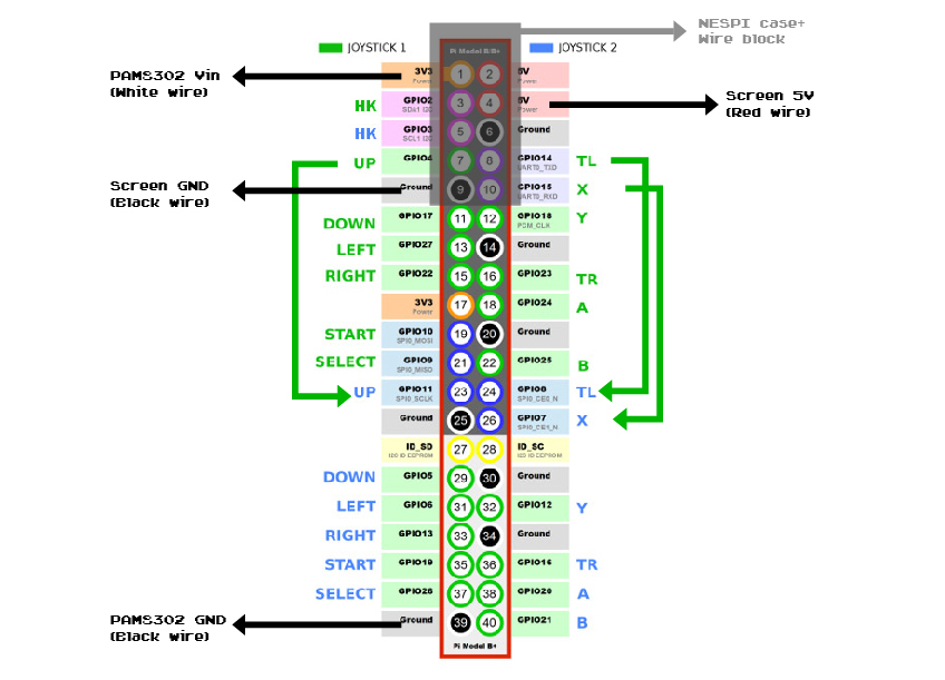
Here is the wiring diagram. In gray is the NESPI wire block where I added the 3 wires to supply the screen and PAM. As GPIO 4, 14, 15 are used by the NESPI, I had to move UP, L and X controls to GPIO 11, 08 and 07 which are those for player 2. I’ll need to set up them later into Recalbox.
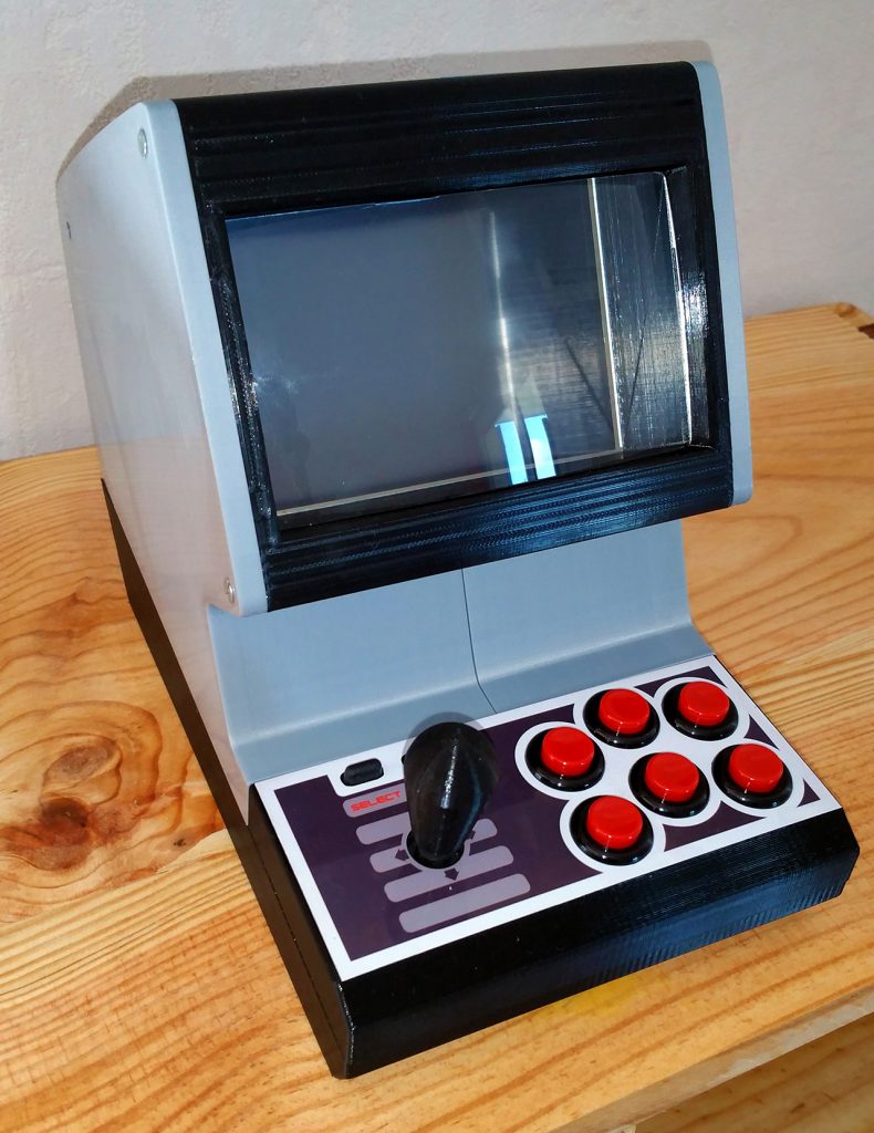
Now that everything is wired, I finish the build. Everything fits perfeclty and I screw the whole thing. Nothing particular here, just not to forget the HDMI cable before installing the screen. For fun, I designed a beautiful NES inspired panel, you can ask me.
SETUP_
As usual, I use Recalbox as system. I start by modifying the config.txt to make the screen work.
I write :
hdmi_group=2
hdmi_mode=87
hdmi_cvt=800 480 60 6 0 0 0
Now, setting up GPIO on recalbox.conf as it’s custom GPIO, section “D2 – GPIO Controllers”, I add :
controllers.gpio.enabled=1

controllers.gpio.args=map=5 gpio=17,11,27,22,10,9,25,24,23,18,7,8,5
By doing this, I tell Recalbox that I’ll use my custom GPIO. I can go later on Recalbox to change control setup.
Et voilà ! It’s over.
CONCLUSION_
Sincerely, I love this build ! Fun to make, much more fun to use ! As I said before, a second version will improve the whole thing, particulary the gameplay. I thinnk soft touch buttons will really make a change. The Sanwas are awesome, button soft touch will make the control more reactive, more like a gamepad and not an arcade panel.
Feel free to go on this project by helping me to improve the Tabletopi_ , if you have any ideas, about the stick, the lens or whatever !
I hope this B_log was usefull, it’s time to say :